When I was in Gradual school at UNC Chapel Hill, there were so many cool graphics projects going on its tough to even remember them all. We had huge mechanical force feedback arms, head mounted displays, all kinds of special purpose hardware including the project I worked on (PixelPlanes).
But we had a really interesting device that mostly sat in the corner and wasn’t used much but I have fond memories of it. It was called the Varifocal Mirror. Here’s the paper about it if you want more info than is in this post. It’s from 1982. If you read the references you can find out that this kind of display dates back to the 1960s (link1, link2)
What I liked about it was that system was a very clever combination of some other devices along with some code.
The core idea from the paper:
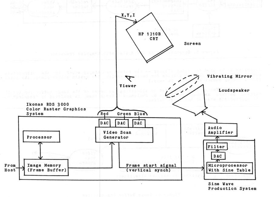
The term varifocal mirror display could as well be called a “vibrating mirror display.” In this kind of system, 3D display is accomplished by the viewer observing the screen not directly, but by looking at a reflection of the screen in a flexible mirror (Figure 1). The mirror consists of flexible material such as aluminized mylar which is stretched taught over a rigid ring, like a drumhead. A loudspeaker mounted closely behind the ring is driven by a smooth sine wave of approximately 30Hz. The viewer’s image of the screen appears extended in depth due to the mirror’s vibrations. (A square image on the screen is extended into roughly rectangular parallelepiped behind the mirror.) Now the major step! The screen is chosen to be a point-plotting CRT with a fast phosphor, and the list of displayed points is refreshed onto the screen at the same rate the mirror is vibrating (30Hz.). Then any particular point will always appear on the screen at the same time in the refresh cycle and thus when the mirror is in the same position, so the point will appear to the viewer to be a particular depth in the parallelepiped. So, any collection of 3D points within the parallelepiped can be displayed simply by placing each 3D point at the place in the refresh buffer determined by its depth (Z) component.
So there were actually two display devices working together to make the display. The first was an oscilloscope/CRT mounted from the ceiling displaying the dots that the user saw when looking down at the mirror. It had inputs for beam intensity and X,Y location on its screen.
The other part of the trick was how to generate these signals? We also had in the lab a programmable frame buffer called an Ikonas which had the normal R,G,B coax outputs you would see back in the day. Someone smarter than me realized you could just hook these up to X,Y, and Intensity to drive the other display. Now you just need to load an “image” into the frame buffer which would generate the dots on the CRT at the times they needed to be there to be in sync with the mirror. The frame buffer refresh is synced to the speaker’s sine wave.
Again from the paper:
This is what it all looked like:
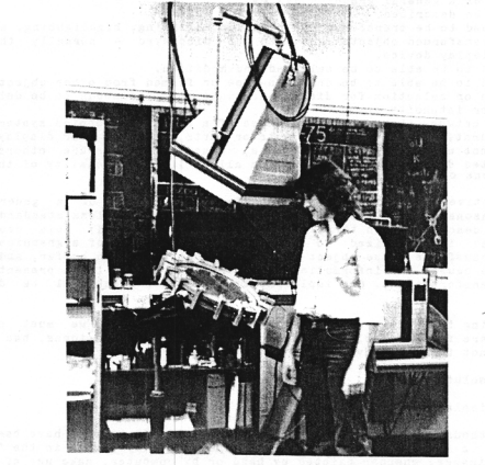
The Ikonas was powerful enough that you could do realtime manipulation of the objects displayed on the device. It was just a point cloud but it really did look 3D w/o any special glasses etc.